EE-106 Basic Electrical Technology Mar-Apr 2026 paper solved: Thevenin, Norton and delta-star bridge
 Nookesh Karri ·· 24 min read

This post solves the AP SBTET C-23 DEEE first year EE-106 Basic Electrical Technology question paper of March/April 2026, question by question. The basic electrical technology question paper 2026 has 10 short questions of 3 marks and 8 long questions of 10 marks, and every one is answered below with circuits, steps and final values. Answers follow the C-23 syllabus and the reference books it prescribes.
Basic Electrical Technology question paper 2026: pattern and syllabus units
The EE-106 paper is for 80 marks in 3 hours. Part A has 10 questions of 3 marks each (30 marks), and you answer all of them. Part B has 8 questions of 10 marks each, and you answer any 5 (50 marks). The marks per unit in this paper match the weightage in the C-23 DEEE curriculum exactly: 19, 23, 29, 13 and 26.
| Q no | Topic | Syllabus unit | Marks |
|---|---|---|---|
| 1 | Ohm’s law | Unit 1 Basic principles of electricity | 3 |
| 2 | Specific resistance, conductance | Unit 1 | 3 |
| 3 | Effect of temperature on resistance | Unit 1 | 3 |
| 4 | KCL and KVL | Unit 2 Resistive circuits | 3 |
| 5 | Energy consumed by a lamp | Unit 3 Work, power, energy, heating | 3 |
| 6 | Joule’s law of heating | Unit 3 | 3 |
| 7 | Thermal efficiency | Unit 3 | 3 |
| 8 | Ideal voltage source | Unit 4 Conversion techniques | 3 |
| 9 | Need for network theorems | Unit 5 Network theorems | 3 |
| 10 | Maximum power transfer theorem | Unit 5 | 3 |
| 11 | R = ρ l / A and a manganin wire sum | Unit 1 | 10 |
| 12 | Series-parallel equivalent resistance | Unit 2 | 10 |
| 13 | Kirchhoff’s laws (branch currents) | Unit 2 | 10 |
| 14 | Monthly electricity bill | Unit 3 | 10 |
| 15 | Metal filament lamp | Unit 3 | 10 |
| 16 | Delta-star transformation | Unit 4 | 10 |
| 17 | Thevenin’s theorem | Unit 5 | 10 |
| 18 | Norton’s theorem | Unit 5 | 10 |
My advice: in Part B pick Q11, Q12, Q14, Q16 and Q18. Each needs one method and short arithmetic, so you can finish it in about 20 minutes and still check it. You can see every EE-106 session together on the Basic Electrical Technology subject page.
Q1. State Ohm’s Law. (3 marks)
Ohm’s law: at constant temperature (and other physical conditions unchanged), the current flowing through a conductor is directly proportional to the potential difference across its ends.
- V ∝ I, so V = I × R, where R is the resistance of the conductor in ohms (Ω).
- Example: a 10 Ω resistor across 5 V carries I = 5 / 10 = 0.5 A.
Key points to write: constant temperature, I ∝ V, V = IR, R in ohms.
Q2. Define (i) specific resistance and (ii) conductance. (3 marks)
(i) Specific resistance (resistivity, ρ): the resistance of a conductor of unit length and unit cross-sectional area of a material, that is, the resistance between opposite faces of a 1 m cube of the material. From R = ρ l / A, ρ = R A / l, and its unit is the ohm-metre (Ω-m).
(ii) Conductance (G): the reciprocal of resistance. It tells how easily a conductor allows current to flow. G = 1 / R, and its unit is the siemens (S) or mho.
Key points to write: ρ = RA/l in Ω-m; G = 1/R in siemens.
Q3. Mention the effects of temperature on resistance in different materials. (3 marks)
The resistance of a material changes with temperature, and different materials change in different ways. The current electricity chapter at Class 12 level shows the same three cases.
- Pure metals (copper, aluminium, silver): resistance increases with rise in temperature. They have a positive temperature coefficient.
- Alloys (manganin, constantan, nichrome): resistance increases very little, so it is almost constant. That is why manganin is used for standard resistors.
- Semiconductors, carbon, insulators and electrolytes: resistance decreases with rise in temperature. They have a negative temperature coefficient.
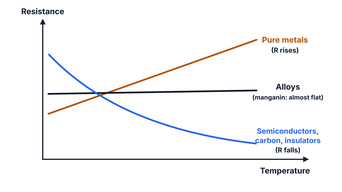
Figure: metals rise, alloys stay nearly flat, semiconductors and insulators fall.
Q4. Define Kirchhoff’s current law and Kirchhoff’s voltage law. (3 marks)
Kirchhoff’s current law (KCL): at any junction (node) of an electric circuit, the algebraic sum of currents is zero: the sum of currents entering a junction equals the sum of currents leaving it: ΣI = 0.
Kirchhoff’s voltage law (KVL): in any closed loop of a circuit, the algebraic sum of all the EMFs and the voltage drops (I × R) is zero: ΣE − ΣIR = 0, or ΣE = ΣIR.
Key points to write: KCL is about currents at a junction (conservation of charge); KVL is about voltages around a closed loop (conservation of energy).
Q5. A lamp which is connected to 230 volts draws a current of 0.261 ampere. Calculate the energy consumed in Joules, if it runs for 10 minutes. (3 marks)
Given: V = 230 V, I = 0.261 A, t = 10 minutes = 10 × 60 = 600 s.
- Power P = V × I = 230 × 0.261 = 60.03 W.
- Energy W = P × t = 60.03 × 600 = 36018 J.
Answer: energy consumed = 36018 J (about 36.02 kJ).
Exam tip: change minutes to seconds. Energy in joules needs time in seconds; energy in kWh needs time in hours.
Q6. State Joule’s law of heating. (3 marks)
Joule’s law: when a current I flows through a resistance R for a time t, the heat produced is directly proportional to:
- the square of the current (H ∝ I²),
- the resistance of the conductor (H ∝ R),
- the time for which the current flows (H ∝ t).
So H = I² R t joules. In calories, H = I² R t / J, where J is the mechanical equivalent of heat (joules per calorie).
Key points to write: H ∝ I², H ∝ R, H ∝ t; H = I²Rt J.
Q7. Define thermal efficiency. (3 marks)
Thermal efficiency is the ratio of the heat usefully used (for example, the heat taken up by the water in a kettle) to the total heat produced by the electrical energy supplied.
- η = (useful heat output) / (total heat produced) × 100 %.
- It is always less than 100 % because some heat is lost to the container and the surroundings by conduction, convection and radiation.
Key points to write: ratio of useful heat to total heat produced; no unit; given as a percentage.
Q8. Define ideal voltage source and mention its characteristics. (3 marks)
An ideal voltage source is a source that keeps a constant terminal voltage across its terminals, whatever current the load draws from it.
Characteristics:
- Its internal resistance is zero.
- Terminal voltage V = E for every load current, so its V-I graph is a horizontal straight line.
- It is drawn as a battery or a circle with + and − signs, with no series resistance. A practical source has a small internal resistance r in series, so V = E − I r falls with load.
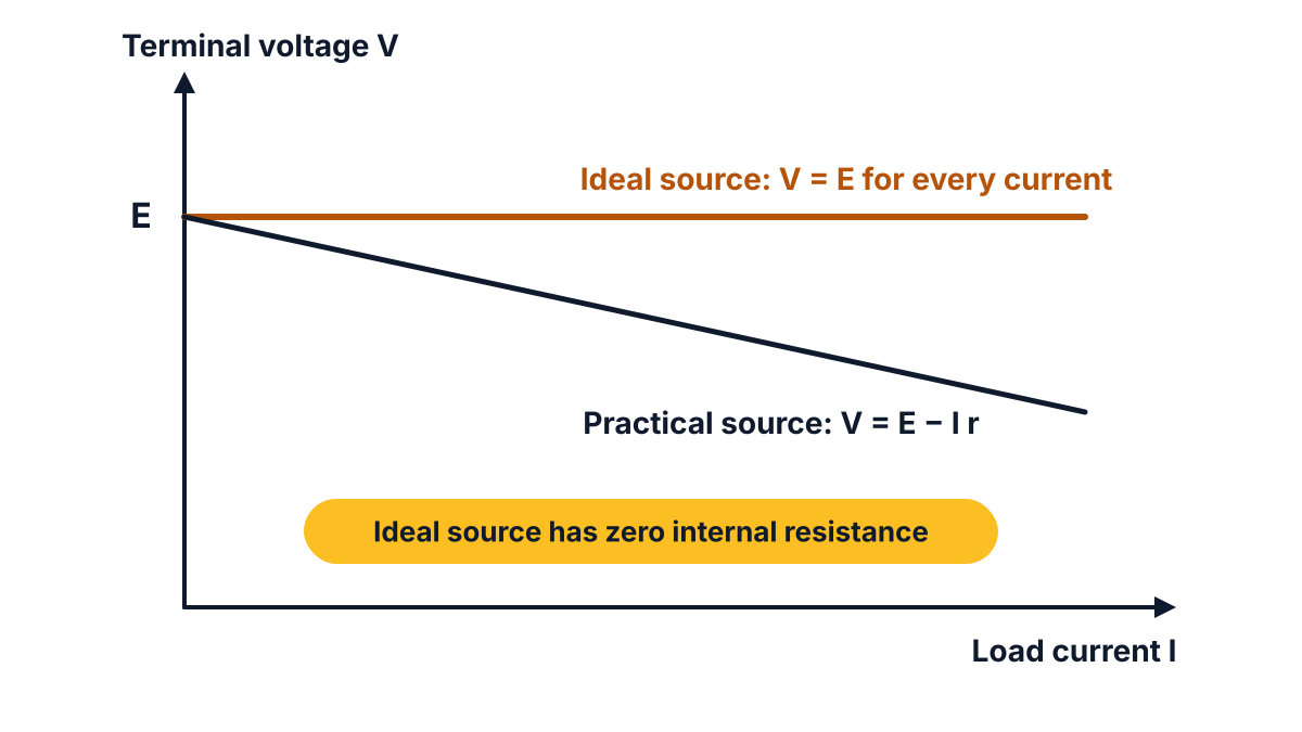
Figure: the flat line is the ideal source; the falling line is a practical source.
Q9. State the need for network theorems. (3 marks)
Network theorems are needed because large networks are hard to solve by KCL and KVL alone.
- A complex network gives many simultaneous equations with KCL and KVL.2. They replace a large network by a simple equivalent circuit (one source and one resistance), as in Thevenin’s and Norton’s theorems.
- They let you find the current in one branch, or the effect of a changing load, without solving the whole network again each time.
Key points to write: simplify complex networks, find the current in one branch quickly, study changing loads.
Q10. State maximum power transfer theorem. (3 marks)
Maximum power transfer theorem: a DC source (or network) delivers maximum power to a load resistance when the load resistance equals the internal resistance of the source, that is, the Thevenin resistance of the network seen from the load terminals.
- Condition: RL = Rth.
- Maximum power: Pmax = Vth² / (4 Rth).
- At this condition the efficiency is only 50 %, because the same power is lost inside the source.
Example from this paper: in Q17, Vth = 32 V and Rth = 4.667 Ω, so Pmax = 32² / (4 × 4.667) = 54.86 W when RL = 4.667 Ω.
Q11. (a) Derive the relation R = ρ l / A. (b) Find the resistance of a 100 m manganin wire of 0.1 mm² cross-section, resistivity 100 × 10⁻⁸ Ω-m (10 marks)
This question has two parts of 5 marks each.
(a) Derivation of R = ρ l / A (5 marks)
Take a conductor of uniform cross-sectional area A and length l, made of one material, at a constant temperature.
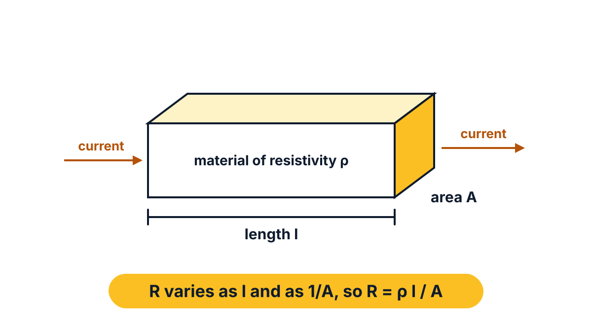
Figure: current flows along the length l through the area A.
- Effect of length. Two equal pieces joined end to end act as two resistances in series, so the resistance doubles. Hence R ∝ l.
- Effect of area. Two equal pieces placed side by side act as two resistances in parallel, so the resistance halves while the area doubles. Hence R ∝ 1 / A.
- Combining the two: R ∝ l / A.
- Removing the sign of proportionality: R = ρ l / A, where ρ is a constant for the material at a given temperature. It is called the specific resistance or resistivity.
- If l = 1 m and A = 1 m², then R = ρ. So resistivity is the resistance of a 1 m cube of the material.
- Unit: ρ = R A / l = (Ω × m²) / m = Ω-m.
(b) Resistance of the manganin wire (5 marks)
Given: l = 100 m, A = 0.1 mm², ρ = 100 × 10⁻⁸ Ω-m.
- Change the area to m²: 1 mm² = 10⁻⁶ m², so A = 0.1 × 10⁻⁶ m² = 1 × 10⁻⁷ m².
- ρ = 100 × 10⁻⁸ = 1 × 10⁻⁶ Ω-m.
- R = ρ l / A = (1 × 10⁻⁶ × 100) / (1 × 10⁻⁷).
- R = (1 × 10⁻⁴) / (1 × 10⁻⁷) = 1 × 10³ Ω.
Answer: R = 1000 Ω (1 kΩ).
Exam tip: most mistakes here come from mm². 1 mm = 10⁻³ m, so 1 mm² = 10⁻⁶ m², not 10⁻³ m².
Q12. Find the equivalent resistance between points A and B terminals for the circuit shown below (10 marks)
The circuit has seven resistors. To solve it, name the two inner junctions P and Q, then combine the resistors step by step from the inside out. Let “||” mean “in parallel with”: R1 || R2 = R1 R2 / (R1 + R2).
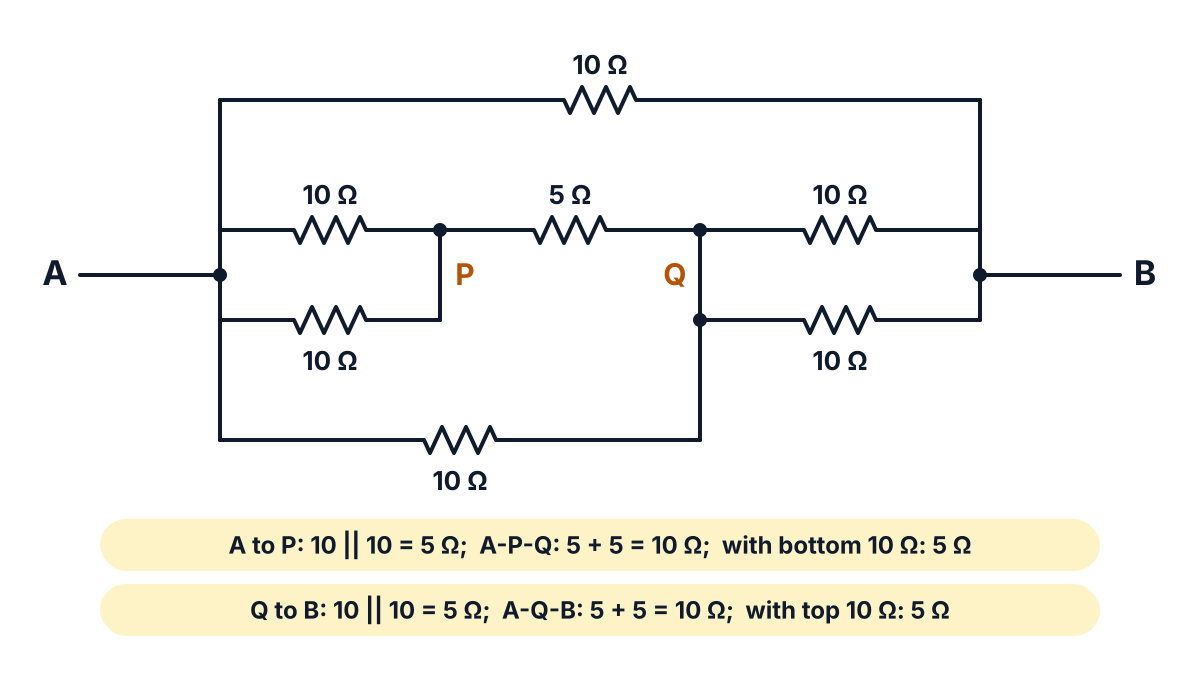
Figure: the paper’s network with the two inner junctions named P and Q.
Reading the figure: the left vertical wire is node A, and the right vertical wire is node B.
- Two 10 Ω resistors join A to P (one above the other).
- The 5 Ω joins P to Q.
- The bottom 10 Ω joins A to Q (the wire from its right end goes up to Q).
- Two 10 Ω resistors join Q to B.
- The top 10 Ω joins A directly to B.
Steps:
- A to P: 10 || 10 = (10 × 10) / (10 + 10) = 5 Ω.
- A to Q through P: 5 Ω + 5 Ω (series) = 10 Ω.
- This 10 Ω is in parallel with the bottom 10 Ω (also A to Q): 10 || 10 = 5 Ω.
- Q to B: 10 || 10 = 5 Ω.
- A to B through Q: 5 Ω + 5 Ω (series) = 10 Ω.
- This 10 Ω is in parallel with the top 10 Ω (A to B): 10 || 10 = 5 Ω.
Answer: equivalent resistance between A and B, RAB = 5 Ω.
Exam tip: redraw the network with node letters before you combine anything. The bottom 10 Ω goes from A to Q, not from A to B; students who miss this get a wrong answer.
Q13. Using Kirchhoff’s laws, find the current through 20 Ω resistor in the circuit shown below (10 marks)
The circuit has a 50 V battery with 15 Ω on the left, a 100 V battery with 30 Ω on the right, and a 20 Ω resistor in the middle branch. Both batteries have their positive terminal at the top. Use the branch current method, as the C-23 syllabus asks.
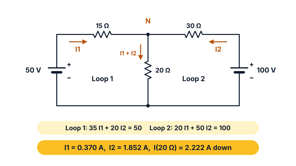
Figure: assumed branch currents I1 and I2 and the two loops.
Step 1: assume branch currents (KCL). Let I1 flow from the 50 V battery through 15 Ω to the top junction N. Let I2 flow from the 100 V battery through 30 Ω to N. By KCL at N, the current down the 20 Ω is (I1 + I2).
Step 2: KVL in loop 1 (50 V, 15 Ω, 20 Ω):
- 50 − 15 I1 − 20 (I1 + I2) = 0
- 35 I1 + 20 I2 = 50 … (i)
Step 3: KVL in loop 2 (100 V, 30 Ω, 20 Ω):
- 100 − 30 I2 − 20 (I1 + I2) = 0
- 20 I1 + 50 I2 = 100 … (ii)
Step 4: solve.
- Multiply (i) by 5: 175 I1 + 100 I2 = 250.
- Multiply (ii) by 2: 40 I1 + 100 I2 = 200.
- Subtract: 135 I1 = 50, so I1 = 0.370 A.
- From (ii): 50 I2 = 100 − 20 × 0.370 = 100 − 7.407 = 92.593, so I2 = 1.852 A.
- Current in 20 Ω = I1 + I2 = 0.370 + 1.852 = 2.222 A.
Step 5: check. Voltage across 20 Ω = 20 × 2.222 = 44.44 V. From the left: 50 − 15 × 0.370 = 44.44 V. From the right: 100 − 30 × 1.852 = 44.44 V. All three agree.
Answer: current through the 20 Ω resistor = 2.222 A (exactly 20/9 A), flowing downward.
Q14. Calculate the monthly electricity bill of a household for 30 days: 4 lamps of 60 W for 8 h, 2 fans of 80 W for 5 h, a 500 W grinder for 2 h and a 1 HP pump at 80 % efficiency for 2 h a day, at ₹3.25 per unit (10 marks)
One unit on the electricity bill is 1 kWh. First find the daily energy of each load in Wh, then the monthly energy in kWh, then multiply by the tariff.
Pump input power. 1 HP is the output of the pump. Take 1 HP (electric) = 746 W. The meter records the input:
Input = output / efficiency = 746 / 0.80 = 932.5 W.
| Load | Daily energy (Wh) | Monthly energy (kWh) for 30 days |
|---|---|---|
| (a) 4 lamps × 60 W × 8 h | 1920 | 57.6 |
| (b) 2 fans × 80 W × 5 h | 800 | 24 |
| (c) 1 grinder × 500 W × 2 h | 1000 | 30 |
| (d) 1 pump × 932.5 W × 2 h | 1865 | 55.95 |
| Total | 5585 | 167.55 |
- Total energy per day = 5585 Wh = 5.585 kWh.
- Energy per month = 5.585 × 30 = 167.55 kWh = 167.55 units.
- Bill = units × rate = 167.55 × 3.25 = ₹544.54 (₹544.5375 rounded to the nearest paisa).
Answer: monthly electricity bill = ₹544.54 (about ₹545).
Exam tip: do not put 746 W directly for the pump. The 80 % efficiency means the pump takes more power from the supply than it gives out, so divide by 0.8.
Q15. Explain the construction and working of metal filament lamp with neat sketch. (10 marks)
A metal filament lamp (incandescent lamp) is an application of the heating effect of electric current. A thin tungsten wire is heated by current until it glows white hot and gives out light.
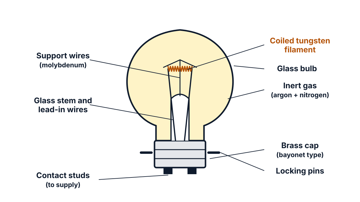
Figure: parts of a gas-filled metal filament lamp.
Construction
- Glass bulb: a thin glass envelope that holds the filament and the gas, and lets light out.
- Filament: a fine wire of tungsten, wound into a coil (or a coil of a coil). Tungsten is used because it has a very high melting point (about 3,382 °C), high resistivity, and can be drawn into a fine wire. Coiling packs a long wire into a small space and reduces heat loss to the gas.
- Support wires: thin molybdenum wires hold the filament in place.
- Lead-in wires: two wires sealed through the glass stem carry current from the cap to the filament.
- Gas filling: lamps of 40 W or more are filled with an inert gas, mostly argon with a little nitrogen. The gas reduces evaporation of the tungsten. The nitrogen prevents arcing between the lead-in wires. Low-wattage lamps are vacuum lamps.
- Cap (base): a brass bayonet cap with two locking pins and two contact studs, or a screw cap. It fits into the holder and connects the lamp to the supply.
Working
- When the switch is closed, current flows through the lead-in wires and the filament.
- The filament has a high resistance, so heat is produced in it by Joule’s law, H = I²Rt.
- The filament temperature rises until it becomes white hot and emits light. This is called incandescence.
- Most of the energy comes out as heat (infrared). Only about 10 % of the output of a typical incandescent lamp is visible light, so its efficiency is low.
- Tungsten that evaporates over time settles on the glass and blackens the bulb. Finally the filament becomes thin and breaks, and the lamp fuses.
Key points to write: tungsten coiled filament, molybdenum supports, inert gas (argon + nitrogen) or vacuum, bayonet or screw cap, I²Rt heating, incandescence, low efficiency.
Q16. Determine the equivalent resistance between terminals A and D of the circuit shown below by using Delta/Star transformation (10 marks)
The bridge has AB = 3 Ω, AC = 6 Ω, BC = 9 Ω, BD = 4.5 Ω and CD = 3 Ω. It is not balanced (3/4.5 is not equal to 6/3), so the 9 Ω cannot be removed. Convert the delta ABC into an equivalent star.
Delta to star formulae. For a delta with RAB, RBC, RCA, the star resistances to a new star point N are:
- RA = (RAB × RCA) / (RAB + RBC + RCA)
- RB = (RAB × RBC) / (RAB + RBC + RCA)
- RC = (RBC × RCA) / (RAB + RBC + RCA)
Each star arm = (product of the two delta resistances meeting at that terminal) / (sum of the three).
Step 1: sum of delta resistances. 3 + 9 + 6 = 18 Ω.
Step 2: star resistances.
- RA = (3 × 6) / 18 = 18 / 18 = 1 Ω.
- RB = (3 × 9) / 18 = 27 / 18 = 1.5 Ω.
- RC = (9 × 6) / 18 = 54 / 18 = 3 Ω.
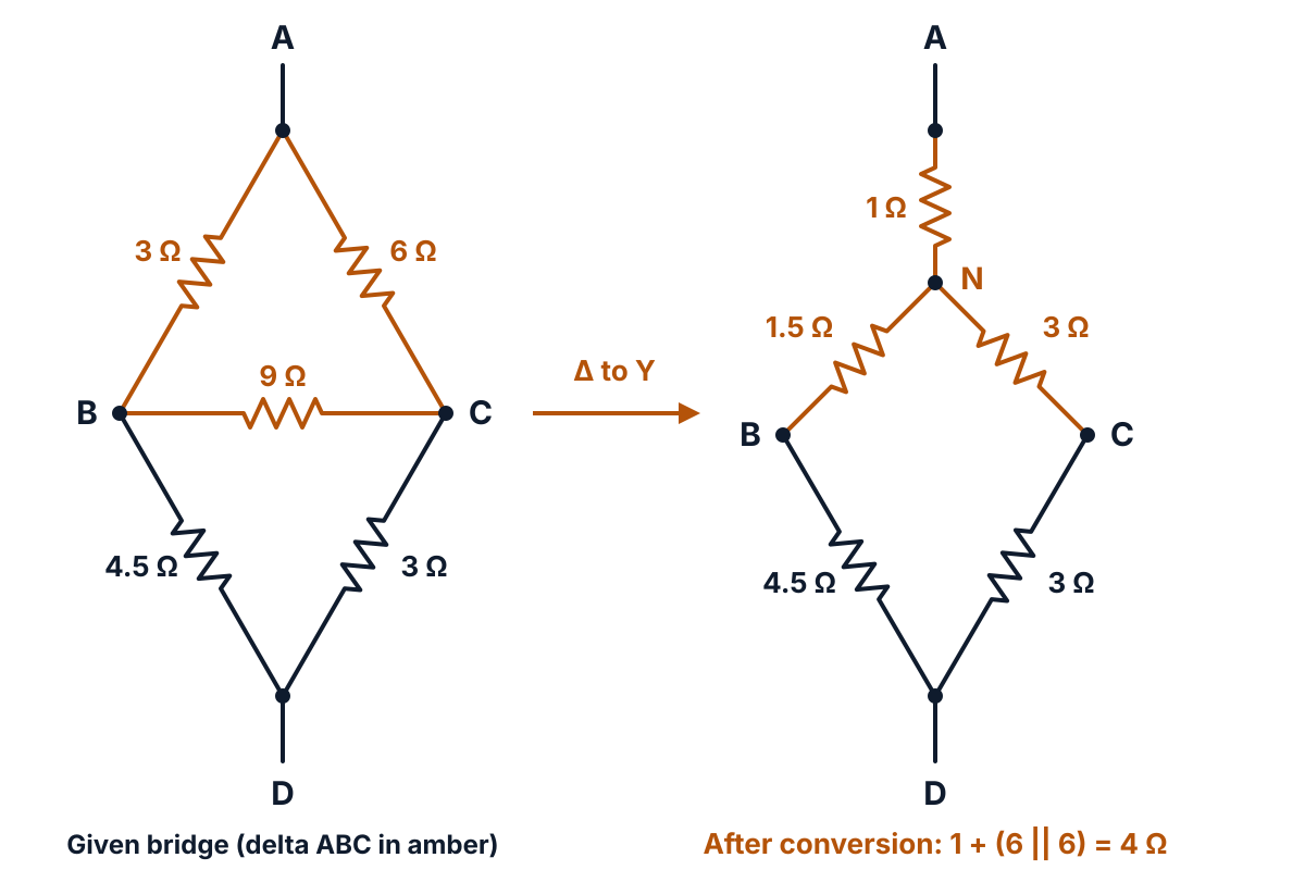
Figure: the delta ABC (amber) becomes a star with point N.
Step 3: simplify the new circuit.
- Path N-B-D: 1.5 + 4.5 = 6 Ω (series).
- Path N-C-D: 3 + 3 = 6 Ω (series).
- These two paths are in parallel between N and D: 6 || 6 = (6 × 6) / (6 + 6) = 3 Ω.
- A to D = RA + 3 = 1 + 3 = 4 Ω.
Answer: equivalent resistance between A and D, RAD = 4 Ω. A nodal check of the original bridge gives the same 4 Ω.
Q17. Find the current through 24 Ω resistor in the circuit shown below by using Thevenin’s theorem (10 marks)
Misprint: the question says 24 Ω, but the figure has no 24 Ω resistor; the load between A and B is 10 Ω (the same figure as Q18), so solve for the 10 Ω load and add one line for 24 Ω.
Thevenin’s theorem: any linear two-terminal network of sources and resistances can be replaced, as seen from the load terminals A and B, by one voltage source Vth in series with one resistance Rth. Then the load current is IL = Vth / (Rth + RL).
Circuit: 48 V source, 4 Ω in series, 8 Ω across, then 2 Ω in series to terminal A; B is the bottom line; load RL = 10 Ω across A-B.
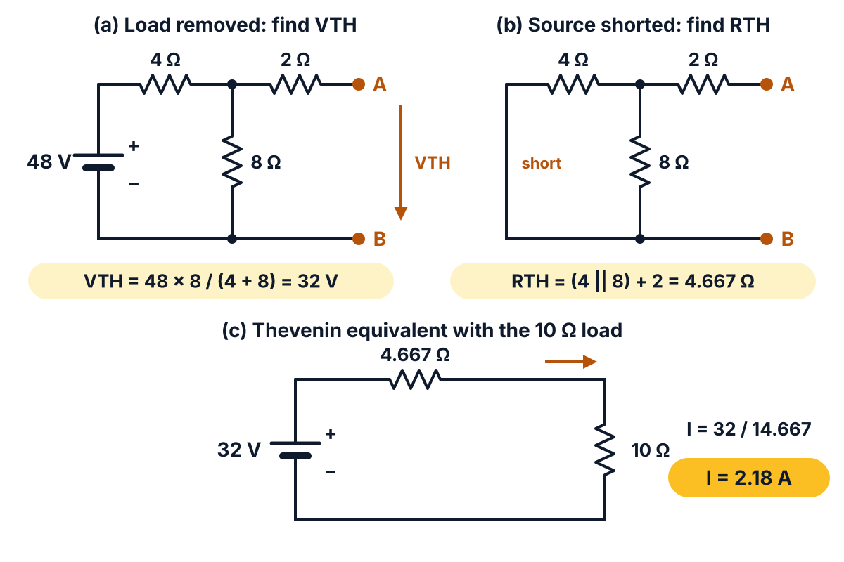
Figure: the three Thevenin steps for the 10 Ω load.
Step 1: remove the load and find Vth. With A-B open, no current flows in the 2 Ω, so Vth is the voltage across the 8 Ω.
- Current in the 4 Ω and 8 Ω = 48 / (4 + 8) = 4 A.
- Vth = 4 × 8 = 32 V.
Step 2: find Rth. Replace the 48 V source by a short circuit (an ideal source has zero internal resistance). Look into A-B:
- 4 Ω || 8 Ω = (4 × 8) / (4 + 8) = 2.667 Ω.
- Rth = 2.667 + 2 = 4.667 Ω.
Step 3: connect the load to the Thevenin equivalent.
- IL = Vth / (Rth + RL) = 32 / (4.667 + 10).
- IL = 32 / 14.667 = 2.182 A.
Answer: current through the load (10 Ω as drawn) = 2.18 A. If the load were really 24 Ω, IL = 32 / (4.667 + 24) = 32 / 28.667 = 1.116 A.
Q18. By using Norton’s theorem find the current through 10 Ω resistor for the circuit shown below (10 marks)
Norton’s theorem: any linear two-terminal network can be replaced, as seen from the load terminals A and B, by one current source IN in parallel with one resistance RN. IN is the short-circuit current between A and B, and RN is the resistance seen from A-B with the sources replaced by their internal resistances. The circuit is the same as in Q17.
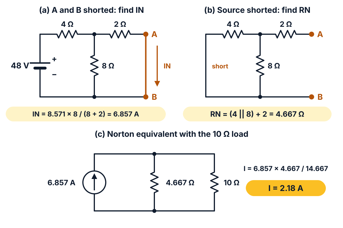
Figure: the three Norton steps; the arrow in the circle shows the source current direction.
Step 1: short A and B and find IN.
- With A-B shorted, the 2 Ω is in parallel with the 8 Ω: 8 || 2 = (8 × 2) / (8 + 2) = 1.6 Ω.
- Total resistance across the source = 4 + 1.6 = 5.6 Ω.
- Source current = 48 / 5.6 = 8.571 A.
- By current division, IN (current in the 2 Ω and the short) = 8.571 × 8 / (8 + 2) = 6.857 A.
Step 2: find RN. Short the 48 V source and look into A-B: RN = (4 || 8) + 2 = 2.667 + 2 = 4.667 Ω.
Step 3: connect the 10 Ω load to the Norton equivalent. By current division:
- IL = IN × RN / (RN + RL) = 6.857 × 4.667 / (4.667 + 10).
- IL = 32 / 14.667 = 2.182 A.
Answer: current through the 10 Ω resistor = 2.18 A. This matches Q17: IN × RN = 6.857 × 4.667 = 32 V = Vth, so the Norton and Thevenin equivalents agree.
Exam tip: in Norton’s theorem the 2 Ω does not drop out. With A-B shorted it comes in parallel with the 8 Ω, so the source sees 5.6 Ω, not 4 Ω.
FAQ
Which units carry the most marks in the EE-106 Mar-Apr 2026 paper?
Unit 3 (work, power, energy and heating effects) carries 29 marks and Unit 5 (network theorems) carries 26 marks. Together they are more than two thirds of the 80 marks, so practise the electricity bill sum, the filament lamp and the Thevenin and Norton problems first.
Which Part B questions should I choose in this paper?
Q11, Q12, Q14, Q16 and Q18 are the safest five. They are short calculations with one clear method each. Q13 and Q17 are also easy if you are good at simultaneous equations and Thevenin’s theorem.
What is wrong with Q17 in the EE-106 March 2026 paper?
Q17 asks for the current in a 24 Ω resistor, but the figure has no 24 Ω resistor. The load between A and B is 10 Ω, the same figure as Q18. Solve it for the 10 Ω load (2.18 A) and add one line for a 24 Ω load (1.116 A).
Do I divide by efficiency for the water pump in a bill problem?
Yes. The 1 HP rating of a pump is its output. The meter records the input, so input power = 746 W ÷ 0.8 = 932.5 W. Using 746 W directly gives a wrong bill.
Sources
- AP SBTET C-23 DEEE EE-106 question paper, Mar-Apr 2026
- C-23 Curriculum, Diploma in Electrical and Electronics Engineering, SBTET AP
- Reference books (C-23 syllabus):
- B.L. Theraja: Electrical Technology Vol. 1, S. Chand
- V.K. Mehta: Introduction to Electrical Engineering
- J.B. Gupta: A Course in Electrical Technology, Katson Books
- G.B. Bharadwajan & A. Subba Rao: Elements of Electrical Engineering
- William H. Hayt: Engineering Circuit Analysis, Tata McGraw-Hill
- NCERT Physics Part I, Class 12, Chapter 3: Current Electricity
- Conversion and equivalency factors, Nebraska Department of Water, Energy and Environment
- Incandescent Light, Encyclopedia.com
Writes and reviews the SBTET EEE Papers solutions: AP SBTET diploma question papers answered step by step from the prescribed syllabus.